Heat conduction in solids¶
How hot each part of a robot gets, and where on it (RFC 0012). Give a link a material and heat
sources, and the thermal domain’s conduction fidelity cuts the link into small cubes (cells),
works out the temperature of every cell, passes heat between neighbouring cells and across to
the parts it is bolted to, and loses it to the air and the sky from every outside face. An LED
on a board, a motor driver on a heat sink and a battery in a closed housing are the usual cases.
flowchart LR
    SRC["heat sources<br/>(1 − η)·P in a box"] --> C
    LOSS["loss_power signals<br/>(motor, battery)"] --> C
    C["cells of each link<br/>conduction, contacts"] --> OUT["thermal/L/temperature,<br/>max, min, heat_flow_out"]
    C --> S["thermal/S/temperature<br/>(each source's box)"]
    AIR["env/air_temperature, airspeed"] --> C
    SKY["env/sky_temperature, sun"] --> C
It runs every 100 ms beside the lumped network (ThermalAPI_1 nodes keep working), whenever a
link has a thermal material and the site’s ambient temperature is given (--ambient-temperature K or the profile’s thermal.ambient_temperature; there is no default).
Using it¶
In a URDF, on the link:
<gazebo reference="led_board">
  <!-- in-plane 20 W/(m·K) from its copper planes, through the board 0.3 -->
  <thermal_material preset="fr4" conductivity="20" conductivity_along="0.3" axis="0 0 1"
                    contact_conductance="3000"/>
  <heat_source name="led_1" power="3.0" efficiency="0.35" xyz="0.01 0 0.0016"
               size="0.003 0.003 0.001"/>
  <heat_source name="driver" power_signal="motor/left/loss_power"/>
</gazebo>
<gazebo reference="heat_sink">
  <thermal_material preset="aluminium_6061" emissivity="0.85"/>  <!-- anodised -->
</gazebo>
or the same in an overlay or USD (ThermalMaterialAPI_1, HeatSourceAPI_1:<name>; formats.md
§3.13). Then run with the site’s ambient temperature:
lagrange_server --robot lamp.urdf --world none --ambient-temperature 298.15
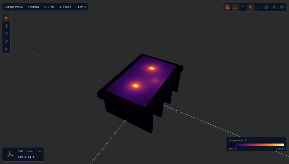
The viewer’s Thermal shading (Shading menu, or --shading thermal) colours every outside face
of each link’s cells by its temperature (the server’s field thermal/cells, one FieldVolume
per link in its frame, 5 times a second), with the legend’s range from the coldest to the
hottest cell. The sample above is assets/robots/led_heatsink/led_heatsink.urdf:
lagrange assets/robots/led_heatsink/led_heatsink.urdf --ambient-temperature 298.15 --rtf 60 \
    -- --shading thermal
# or: lagrange_server --robot assets/robots/led_heatsink/led_heatsink.urdf --world none \
#       --ambient-temperature 298.15 --rtf 60
For the steady temperatures alone, at rest and without physics, in a second or two:
lagrange heat --robot assets/robots/led_heatsink/led_heatsink.urdf --world none \
    --ambient-temperature 298.15 [--surface-coefficient H] [--cell M]
prints each link’s mean, max and min and each source’s temperature, and the heat in and out. A source on a power signal takes no power there (nothing drives it).
Signals, per link L with a material and per source S:
Signal |
Unit |
|
|---|---|---|
|
K |
the link’s volume average |
|
K |
its hottest and coldest cell |
|
W |
to the air and the sky |
|
1 |
1 once any cell reaches |
|
K |
the average over the source’s box (the case temperature) |
|
W |
|
|
W |
|
Profile keys (domains.thermal): fidelity (conduction, the default when a link has a
material, or lumped to leave the materials out), cell (m, default 0.002), max_cells (per
link, default 200000), surface_coefficient (W/(m²·K): one film coefficient for every face
instead of the correlations below).
Temperature sensors¶
A thermal camera (ThermalCameraAPI_1, docs/physics/sensors.md) reads a link with a thermal
material at its thermal/<L>/temperature with the material’s emissivity: bare aluminium
(0.09) reads near the room’s temperature however hot it is, as through a real camera; paint
or anodising (0.8 to 0.9) close to its own.
The sample plugin lagrange_thermal_probe (core/plugin_abi/samples/thermal_probe.c, C ABI,
--plugin lagrange_thermal_probe) reads the thermal domain like a real sensor:
<gazebo reference="led_board">
  <sensor name="led_ntc" type="thermistor">
    <update_rate>10</update_rate>
    <thermistor><target>led_left</target><time_constant>2.0</time_constant>
      <noise><stddev>0.05</stddev></noise><resolution>0.0625</resolution></thermistor>
  </sensor>
</gazebo>
<gazebo reference="camera_arm">
  <sensor name="board_ir" type="ir_thermometer">
    <pose>0 0 0 0 1.5708 0</pose>  <!-- looking down -->
    <ir_thermometer><fov>0.2</fov><range>0.5</range><emissivity>0.95</emissivity>
      <ambient>298.15</ambient></ir_thermometer>
  </sensor>
</gazebo>
thermistor, a contact sensor:thermal/<target>/temperature(a heat source’s case, a link’s mean, a lumped node; default its own link) through a first-order lag oftime_constants, with Gaussiannoise/stddev(K) and quantisation toresolution(K; 0.0625 for a 12-bit digital sensor). Outputsensor/<name>/temperature.ir_thermometer, a spot pyrometer along its +x: a 5 × 5 grid of rays overfov(rad, 0 one ray) torange; what each ray meets is seen at its link’s temperature with the targetemissivityset on the sensor (as on a real one), the rest of the radiance reflected from the surroundings, so the reading is \((\overline{\varepsilon T^4 + (1-\varepsilon)T_{amb}^4})^{1/4}\) (broadband, not in the sensor’s band). The ambient isenv/air_temperaturewhen the weather runs, elseambient(no default). Outputssensor/<name>/temperature,valid.
Checked by test_plugins’ TheThermalProbesReadTheHeatConduction: the thermistor lags its LED
while it heats and meets it within 0.1 K; the infrared reading equals the grey-body formula for
the board’s temperature within 0.05 K.
In OpenFOAM: lagrange foam-cht¶
When the air’s flow matters (a fan, a duct, parts that warm each other’s air), give the same robot to OpenFOAM’s conjugate heat transfer solver:
lagrange foam-cht assets/robots/led_heatsink/led_heatsink.urdf --ambient 298.15 --out led_case
It writes a chtMultiRegionSimpleFoam case (tools/cli/lagrange_foam_cht): a solid region per
link with a material (its collision surfaces, lagrange tunnel --export-surface), still air
around them with buoyancy (laminar, the box’s walls at the ambient, its top open), each heat
source as a scalarSemiImplicitSource on the cells of its box, a contact conductance as a thin
layer on the child’s side of the interface, an orthotropic board as constAnIso. The numbers
come from lagrange export thermal ROBOT --out FILE.json, the same reading of the URDF as the
conduction fidelity’s. It runs with an installed OpenFOAM or the container
(opencfd/openfoam-default:2512, --procs processes), reads each region’s mean, max and min and
each source’s mean into report.json, and --compare RUN.json sets a Lagrange run’s beside them;
--start-from RUN.json starts the solids at its temperatures, which shortens the iterations (the
coupled solids converge slowly from the ambient). OpenFOAM is GPL-3 and stays a separate program:
files only. --radiation adds surface radiation through the air by discrete ordinates (fvDOM,
3 × 3 directions per octant): each solid’s faces at its emissivity, the box’s walls black at the
ambient. Without it, compare it with a run whose emissivities are 0.
The sample against OpenFOAM (2026-11-11; led_heatsink.urdf with its emissivities set to
0, 298.15 K; each case run until no temperature moved by 0.01 K; Lagrange run for an hour of
simulated time to steady state, 3.000 W in and out). The OpenFOAM answer depends strongly on its
mesh (--cells-through, cells through the thinnest shape): the air’s thin boundary layer at each
face is what carries the heat away, and coarse cells smear it into a still layer that insulates.
mesh |
cells |
sink, mean |
LED |
LED over the sink |
|---|---|---|---|---|
1 through the board ( |
96,000 |
the solver fails (warned since) |
||
2 through ( |
203,000 |
353.2 K |
379.4 K |
26.2 K |
4 through ( |
640,000 |
344.5 K |
384.0 K |
39.5 K |
8 through ( |
2,490,000 |
325.5 K |
364.0 K |
38.4 K |
Lagrange, the correlations |
20,788 |
325.5 K |
352.9 K |
27.4 K |
lagrange foam-cht now defaults to --cells-through 4 and those under-relaxations. On the
finest mesh OpenFOAM’s sink sits where Lagrange’s correlations put it (325.5 K both, a
27.4 K rise). Coarser meshes leave the sink up to twice as hot, so a coarse foam-cht run is not
a reference for the film coefficient. Use --cells-through 4 or more, and check one mesh finer.
The three meshes do not converge monotonically, so the finest is not shown to be converged
either. Inside the solids, the LED’s hot spot over the sink is 38 K on the two finer meshes
against Lagrange’s 27 K. Lagrange spreads the LED’s heat over its 3 mm box on 0.8 mm cells, and
OpenFOAM’s cells under the LED are four to eight times smaller. The hot spot depends on how
finely the source’s box is cut, in both codes, and neither has converged. Lagrange’s LED reads
352.9 K on 0.8 mm cells, 365.5 K on 0.4 mm and 357.3 K on 0.125 mm
(lagrange heat --cell M). OpenFOAM’s reads 379.4, 384.0 and 364.0 K on its three meshes. Read a
source’s temperature to within about 10 K, and the link’s mean and the sink much closer.
With radiation (the sample at its own emissivities, 0.85 and 0.9; --radiation, the default
mesh only):
OpenFOAM (203,000 cells) |
Lagrange |
|
|---|---|---|
sink, mean |
334.5 K |
317.6 K |
LED, case |
360.2 K |
344.8 K |
Radiation takes about a third of the rise off in both (OpenFOAM 55 to 36 K over the air, Lagrange 27 to 19 K). On this mesh the convection is under-resolved as above, so the gap is mostly that. Each of Lagrange’s faces radiates in the share of its surroundings it sees (below). Without that share it radiated more from between the fins.
The model¶
Cells. Each link is cut into cubes in its own frame from its collision shapes (boxes,
spheres, cylinders, capsules, convex hulls). A cube is solid when its centre is inside a shape.
The cube side is cell, but at most half the link’s thinnest shape (so a 1.6 mm board has two
cells through it) and coarser when the link would have more than max_cells.
Conduction. Between two neighbouring cells of side \(h\) the conductance is \(k\,h\) (area
\(h^2\) over distance \(h\)). An orthotropic material (conductivityAlong with axis \(\hat a\)) has
\(k_d = k_\perp + (k_\parallel - k_\perp)\,a_d^2\) along each axis \(d\) of the link, exact when the
axis lies along one of them.
Contacts. Where a link’s cell touches its parent link’s cell (the nearest ancestor with a
material, at the joints’ zero positions), the two exchange heat through
\(R = \frac{h_a/2}{k_a A} + \frac{1}{h_c A} + \frac{h_b/2}{k_b A}\) with the child’s
contactConductance \(h_c\). Typical values: bare aluminium on aluminium in air 2,200–12,000
W/(m²·K), with thermal grease about 10⁵, a 1 mm gap pad about 2,000 (Incropera Tables 3.1–3.2;
Bergquist Gap Pad 2500 data sheet). Touching links without one exchange nothing, and the start
logs the pair.
Surfaces. Every other outside face loses \(h\,A\,(T - T_{air})\) and
\(F\,\varepsilon\sigma A (T^2 + T_{sky}^2)(T + T_{sky})(T - T_{sky})\), the radiation exact at the
cell’s temperature of the last step, with \(F\) the share of the surroundings the face sees: of 16
fixed cosine-weighted directions over its hemisphere, those that leave every part’s solid behind
(rest poses). What a face sees of another face, between fins, is about its own temperature, and
its net exchange is left out. A convex part alone has \(F = 1\); two plates 2 mm apart see 0.59 of
theirs (FacesThatSeeEachOtherRadiateLess). The film coefficient \(h\) comes from the link’s mean surface
temperature and its size as it sits now:
vertical faces: Churchill and Chu, \(Nu = \{0.825 + 0.387\,Ra^{1/6}/[1 + (0.492/Pr)^{9/16}]^{8/27}\}^2\) on the link’s height (Incropera Eq. 9.26);
horizontal faces, with \(L = A/P\) of its footprint: the upper face of a hot link (or lower of a cold one) \(0.54\,Ra^{1/4}\) up to \(Ra = 10^7\) and \(0.15\,Ra^{1/3}\) above, the other side \(0.52\,Ra^{1/5}\) (Incropera Eqs. 9.30–9.32); inclined faces blend the two by \(|n_z|\);
forced, with
body/<b>/airspeed: the flat plate over the link’s longest side, \(0.664\,Re^{1/2}Pr^{1/3}\) (laminar) or \((0.037\,Re^{4/5} - 871)Pr^{1/3}\) (Incropera Eqs. 7.30, 7.38), combined as \(h = (h_n^3 + h_f^3)^{1/3}\) (Churchill and Usagi, Incropera Eq. 9.65).
Air is taken at 300 K (Incropera Table A.4: \(\nu = 15.89 \cdot 10^{-6}\) m²/s,
\(k = 0.0263\) W/(m·K), \(\alpha = 22.5 \cdot 10^{-6}\) m²/s, \(Pr = 0.707\)), \(\beta = 1/T_{film}\). With
env/solar_irradiance, faces looking up absorb \(\varepsilon\,G\,n_z\) (the sun overhead, a grey
surface).
Sources. A heat source’s \((1-\eta)P\) is shared over the cells whose centres are in its box (the
nearest cell when none is); a loss_power signal named like the link is spread over all its
cells. A motor (ElectricalMotorAPI_1) with no lumped node of its own heats the link that holds
its stator, its joint’s parent, in a 2 cm box at the joint, with motor/<m>/loss_power (copper
and drive losses, when the electrical network runs), as the source <m>_mount
(thermal/<m>_mount/temperature, the mount’s; the winding’s is a lumped node’s).
Time. Backward Euler over the step, solved by conjugate gradients with a Jacobi preconditioner from the last temperatures, to a relative residual of \(10^{-12}\): stable at any step, the same operations in the same order every run (bit-reproducible, CPU, every tier).
Materials¶
Presets near 300 K. Values marked TODO(verify) in modules/thermal/conduction/src/Materials.cpp
were not read from the primary source.
Preset |
k (W/m·K) |
ρ (kg/m³) |
c_p (J/kg·K) |
ε |
Source |
|---|---|---|---|---|---|
|
167 |
2700 |
896 |
0.09 (anodised ≈ 0.8) |
ASM/MatWeb data sheet |
|
151 |
2680 |
963 |
0.09 |
A356-T6 data sheets |
|
401 |
8933 |
385 |
0.03 |
Incropera Table A.1 |
|
14.9 |
7900 |
477 |
0.075 |
Incropera Table A.1 |
|
0.81 in-plane, 0.29 through |
1850 |
1100 |
0.9 |
IPC data via Wikipedia “FR-4” |
|
0.13 |
1240 |
1800 |
0.9 |
Prusament PLA TDS |
|
0.17 |
1100 |
1400 |
0.9 |
Ultimaker ABS TDS |
|
0.2 |
1270 |
1300 |
0.9 |
Prusament, eSun TDS |
|
0.23 |
1010 |
1600 |
0.9 |
Weerg, Xometry data sheets |
|
0.2 |
1190 |
1200 |
0.9 |
Ultimaker PC TDS |
|
4 in-plane, 0.6 through |
1600 |
750 |
0.85 |
PMC10339322 |
|
1.4 |
2500 |
750 |
0.92 |
Incropera Table A.3 |
|
0.2 |
1200 |
1270 |
0.9 |
— |
|
3 |
3300 |
900 |
0.9 |
Bergquist data sheets |
The orthotropic presets take axis (default the link’s z) as the through direction. A bare FR-4
board spreads heat poorly: 2 W from a 3 mm LED raises it some hundreds of kelvin above the rest
of the board, which is why power LEDs sit on metal-core boards (give the board’s in-plane
conductivity of its copper, e.g. conductivity="20", or model the metal core as its own link).
Checked against¶
modules/thermal/test/test_conduction.cpp:
Case |
Reference |
Result |
|---|---|---|
A 1 cm copper cube cooling at h = 10 |
lumped, \(\exp(-hAt/\rho c V)\) |
within 0.5 % |
A 4 mm aluminium rod, 1 W into one end |
the fin with a convecting tip (Incropera Table 3.4) |
shape within 10⁻⁴, base 0.25 % at 0.5 mm cells, first order |
A steel bar under 10⁵ W/m² |
the semi-infinite solid (Carslaw and Jaeger §2.9) |
within 0.01 % |
Two copper blocks across 2000 W/(m²·K) |
the two-node network |
within 0.1 % |
An orthotropic rod |
the fin with \(k_\parallel\) |
within 2 % |
Two runs |
bit for bit |
equal |
modules/thermal/test/test_thermal_conduction.cpp runs it on the bus (an LED board on a plate,
energy in equals out at steady state), and test_server’s ThermalMaterials.* from a URDF.
Not modelled: the air’s flow (use lagrange foam-cht for conjugate heat transfer in OpenFOAM),
light’s path (the radiant power just leaves), junction temperature, thermal expansion, melting.