Tutorial: test your own drone, step by step¶
This tutorial takes a drone that is not one of Lagrange’s samples, the Holybro X500 V2 (PX4’s
model, in assets/robots/holybro_x500_v2/), and tests it from a first hover up to live computed
air. The same steps work for any multirotor of yours: swap in your URDF and overlay (see
Your own drone at the end).
You need Lagrange built and the Holybro’s meshes fetched once
(ros2 run lagrange_assets fetch_assets holybro_x500_v2).
The videos below are of the sample quadcopter, quad_x500; the Holybro does the same.
The whole path at a glance¶
flowchart TD
    S0["0 · Setup<br/>source, build, make the bem overlay"] --> S1
    S1["1 · Hover<br/>does it lift its own weight?"] --> S2
    S2["2 · Fly it by hand<br/>teleop over /cmd_vel"] --> S3
    S3["3 · Blade-element rotors<br/>quad_x500_bem.yaml"] --> S4
    S4["4 · Downwash in the open<br/>quad_x500_downwash.yaml"] --> S5
    S5["5 · Downwash beside a building<br/>drone_building world"] --> S6
    S6["6 · Live computed air<br/>quad_x500_live_air.yaml, RTX GPU"] --> S7
    S7["7 · Checks without a window<br/>Python, tests, realism.sh"]
    S2 -.->|any time| W["Wind: lagrange set wind_speed=4"]
    S4 -.-> W
Each step adds one physics model on top of the last, so when something looks wrong you know which model to blame.
What goes into a run¶
Every command in this tutorial has the same three inputs:
flowchart LR
    U["Robot file<br/>holybro_x500_v2.urdf<br/>(bodies, joints, meshes)"] --> SRV
    O["Overlay<br/>holybro_x500_v2.overlay.yaml<br/>(rotors, motors, battery, sensors)"] --> SRV
    P["Profile<br/>quad_x500_*.yaml<br/>(which physics is on, air density)"] --> SRV
    SRV["lagrange_server<br/>MuJoCo, electrical, rotor_aero,<br/>aerodynamics, sensors"] --> V["Viewer window<br/>3D, Scopes, Environment"]
    SRV --> ROS["ROS 2<br/>/imu /odom /gnss/fix ..."]
    T["teleop_twist_keyboard"] -->|/cmd_vel| SRV
The robot file is the shape: links, joints, meshes. A plain URDF can’t say “this joint is a rotor with a 10 inch propeller driven by a 920 KV motor”.
The overlay says exactly that:
RotorAPI_1on each rotor joint, a motor on each, a 4S battery, a bus, and the IMU, GNSS, magnetometer and barometer.The profile picks which physics runs and how detailed it is.
The first argument to lagrange is always the profile. The robot goes after --robot and the
overlay after --overlay. Putting the overlay first gives unknown key apply; a run file has ....
How detailed are the rotors?¶
The profiles go from simple to detailed:
flowchart LR
    A["coefficients<br/>T = CT·ρ·n²·D⁴<br/>+ ground effect"] --> B["bem<br/>blade-element momentum<br/>needs propeller files"]
    B --> C["+ downwash<br/>fitted wake model:<br/>jet, outwash, walls, roofs"]
    C --> D["+ live air (lbm)<br/>lattice Boltzmann box<br/>around the drone, GPU"]
    A -.- PA["quad_x500_hover.yaml<br/>quad_x500_gusty.yaml"]
    B -.- PB["quad_x500_bem.yaml"]
    C -.- PC["quad_x500_downwash.yaml"]
    D -.- PD["quad_x500_live_air.yaml"]
The Holybro overlay gives each rotor a thrust and power coefficient (APC 10x4.7 from the UIUC database) but no blade geometry. Steps 3 to 6 need blade geometry, so in step 0 you make a copy of the overlay that names propeller files.
Step 0 · Setup¶
Run these lines in every new terminal:
cd ~/Documents/Research/Lagrange
source /opt/ros/lyrical/setup.bash
source install/setup.bash
Build once, if you haven’t since the last pull:
MAKEFLAGS=-j8 colcon build --symlink-install --parallel-workers 2 \
    --cmake-args -DCMAKE_BUILD_TYPE=RelWithDebInfo
Make the overlay copy with propeller files (generic_10in_2blade, a 10 inch two-blade
propeller, the Holybro’s size):
P=$PWD/assets/propellers
sed -e "s|^\( *\)aero:rotor:direction: ccw|&\n\1aero:rotor:propeller: $P/generic_10in_2blade_ccw.prop.yaml|" \
    -e "s|^\( *\)aero:rotor:direction: cw|&\n\1aero:rotor:propeller: $P/generic_10in_2blade_cw.prop.yaml|" \
    assets/robots/holybro_x500_v2/holybro_x500_v2.overlay.yaml > /tmp/holybro_bem.overlay.yaml
grep -c "aero:rotor:propeller" /tmp/holybro_bem.overlay.yaml     # must print 4
Short names for the rest of the tutorial (set them again in each new terminal):
R="--robot assets/robots/holybro_x500_v2/holybro_x500_v2.urdf"
O="--overlay assets/robots/holybro_x500_v2/holybro_x500_v2.overlay.yaml"
B="--overlay /tmp/holybro_bem.overlay.yaml"
Step 1 · Hover¶
lagrange profiles/examples/quad_x500_hover.yaml $R $O --world none
The terminal shows, among other lines:
[profile] applied; the run restarted at t = 0
[stage] loaded assets/robots/holybro_x500_v2/holybro_x500_v2.urdf · 5 bodies, 5 joints, ...
[controller] multicopter: the built-in controller takes off after 1 s and hovers 2 m above the start
[sensors] IMU imu on base_link at 250 Hz
[sensors] GNSS gnss on base_link at 10 Hz
Two lines at the very top, the rotors do not run without the site's air density and
GNSS ... do not run without the site's geo origin, come from before the profile is applied.
Ignore them when [profile] applied follows.
What happens:
sequenceDiagram
    participant C as Built-in controller
    participant M as Motors (electrical)
    participant R as Rotors (rotor_aero)
    participant P as MuJoCo
    Note over C: t = 0 to 1 s: waits on the ground
    C->>M: torque commands (climb to start + 2 m)
    M->>R: rotor speeds
    R->>P: thrust and drag torque on base_link
    P-->>C: pose and velocity (every 1 ms)
    Note over C,P: holds 2 m, the four thrusts add up to the weight
Check it:
Height: it lifts off after 1 s and stops about 2 m up. In a headless run it settled at z = 2.23 m (it starts at 0.23 m).
Thrust: in the viewer’s Scopes, plot
rotor/rotor_1_joint/thrusttorotor_4_joint. They add up to the weight: 2.064 kg × 9.81 = 20.25 N, so about 5.06 N each. (Measured: 20.24 N.)Battery:
battery/battery/terminal_voltageandbattery/battery/socdrop slowly while it hovers.
Step 2 · Fly it by hand¶
One launch file does steps 1 and 2 together: the server, the viewer following the drone, and
teleop in a window of its own. There the drone waits on the ground until you press t, and b
lands it. It is the example package
lagrange_example_holybro:
ros2 launch lagrange_example_holybro teleop.launch.py
Or by hand: leave step 1 running. In a second terminal (do step 0’s source lines first):
ros2 run teleop_twist_keyboard teleop_twist_keyboard --ros-args -p stamped:=true
Keep that terminal focused while you press keys:
Key |
Does |
|---|---|
|
forward / back |
|
left / right, sideways |
|
turn left / right |
|
up / down |
|
stop |
|
faster / slower |
flowchart LR
    K["keyboard"] --> TT["teleop_twist_keyboard"]
    TT -->|"/cmd_vel TwistStamped<br/>forward, left, up m/s, yaw rate"| CTL["built-in controller"]
    CTL -->|"no command for 0.5 s"| HOLD["holds where it is"]
    CTL --> ROT["4 rotors"]
Check it:
Moving: it goes where you send it and tilts into the motion.
Starting and stopping: the commanded speed ramps at up to 3 m/s² with a jerk limit of 8 m/s³ (PX4’s position-mode defaults), so it leans about 17° to speed up and to brake. When you stop pressing (or 0.5 s after the last command) it brakes to a stop and holds where it stopped.
Ground effect: go down with
bto about 0.3 m and plotjoint/rotor_1_joint/velocity. The rotors slow down: near the ground each turn of the blades gives more thrust, and the controller needs only the weight.Limit: it never descends faster than 2 m/s (the controller’s cap).
Something in the way: fly it up under a roof or into a wall and keep the key down. It presses on with a bounded push (the set point stays within about 0.35 m of the drone, half a g from the position loop), and when you let go it holds right where it is.
Wind, any time from here on: in a third terminal,
lagrange set wind_speed=4 wind_from=270     # 4 m/s from the west
lagrange set wind_speed=0                   # back to still air
For wind in the hover profile, use quad_x500_gusty.yaml instead (8 m/s with Dryden
turbulence). The drone leans into the wind and drifts while the controller catches up.
Step 3 · Blade-element rotors¶
Close step 1’s viewer (that also stops its server), then:
lagrange profiles/examples/quad_x500_bem.yaml $R $B --world none
Now each rotor’s thrust comes from its blades: the twist and chord of every section, the air coming through the disc, and the tip losses.
Check it:
Blades: the propellers are drawn as blades.
Hover: it still hovers at about 2 m, with a slightly different rotor speed (
joint/rotor_1_joint/velocity) than in step 1.Climb: with teleop, climb fast with
tand plotjoint/rotor_1_joint/velocity. The rotors spin faster for the same thrust while climbing, because the air coming in from above unloads the blades. Step 1’s coefficients don’t show that.
Step 4 · Downwash in the open¶
lagrange profiles/examples/quad_x500_downwash.yaml $R $B --world none \
    -- --overlays airflow --slice aero/wind_speed:xz
Everything after -- goes to the viewer: airflow turns on the particles and
--slice aero/wind_speed:xz shows a vertical slice of the air speed.
flowchart TD
    D["4 rotor discs"] --> NW["near wake<br/>4 separate columns"]
    NW --> J["merged jet<br/>(Bauersfeld et al. 2024)"]
    J --> G{"ground<br/>close?"}
    G -->|yes| OW["outwash spreads<br/>along the ground<br/>(Tanner et al. 2015)"]
    G -->|no| J
    WIND["wind"] -.->|skews the wake| J
Check it:
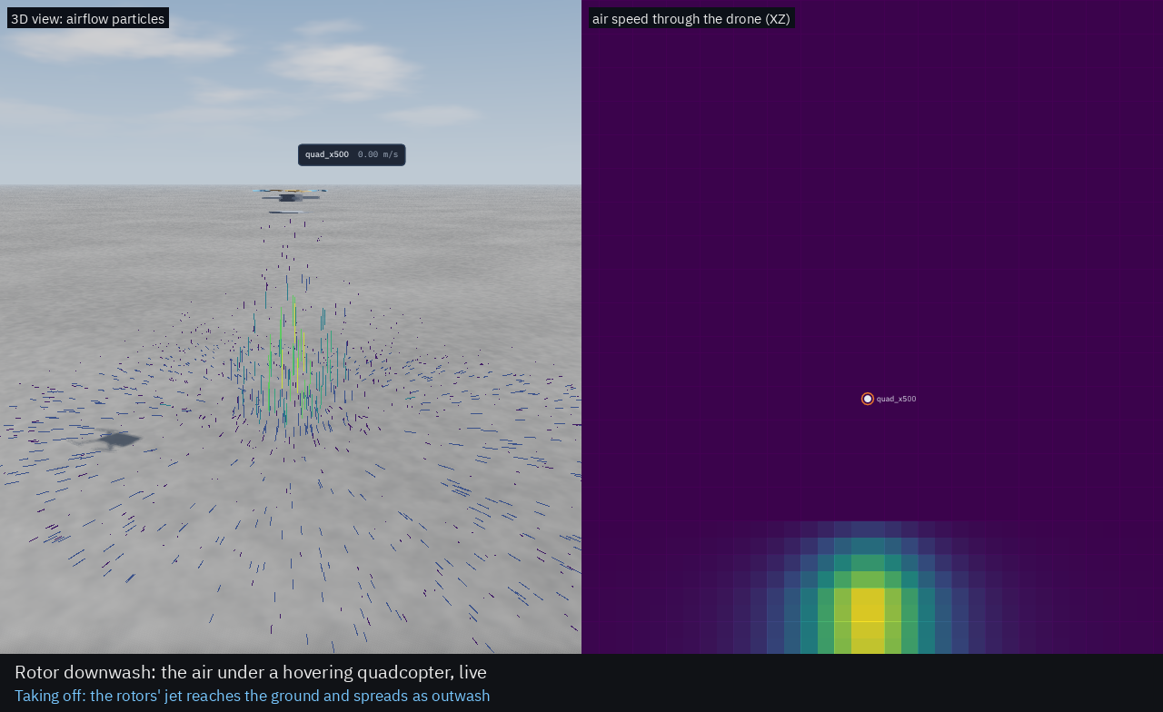
Wake: particles fall in four columns under the rotors, merge into one jet, and spread out along the ground.
Slice: the Environment workspace’s Slice 2D panel shows the same air speed.
Wind:
lagrange set wind_speed=4 wind_from=270, and the wake leans downwind.Low hover: fly down to about 0.5 m. The outwash ring gets wider and faster.
The air under a hovering quadcopter: particles in 3D and its speed through the drone, then leaning in wind
Coming down to half a metre: the outwash ring spreads wide
Step 5 · Downwash beside a building¶
lagrange profiles/examples/quad_x500_downwash.yaml $R $B \
    --world assets/worlds/drone_building/drone_building.urdf -- --overlays airflow
flowchart LR
    subgraph near ["near the wall"]
      NR["near rotors:<br/>more inflow"]
    end
    subgraph far ["away from the wall"]
      FR["far rotors:<br/>less inflow"]
    end
    WALL["wall mirrors the wake"] --> NR
    ROOF["roof: wake stops<br/>and spreads"]
    NR --> CTRL["controller speeds up<br/>the near rotors to stay level"]
Check it:
Beside the wall: fly to about half a metre from it. In Scopes, plot
rotor/rotor_1_joint/air_velocity(itsz) for a rotor near the wall and one away from it. The near rotor gets more air pushed down through it.Controller response: the near rotors’
joint/rotor_N_joint/velocitygoes up, because the controller works to keep the drone level.Over the roof: climb with
tand fly over the roof. The wake stops on the roof and spreads over it instead of reaching the ground.
Beside a 12 m building and over its roof: the wake hugs the wall and spreads on the roof
Step 6 · Live computed air (RTX GPU)¶
lagrange profiles/examples/quad_x500_live_air.yaml $R $B --world none
This puts a 3 m box of lattice Boltzmann air, with 4 cm cells, around the drone. It follows the drone and runs on the GPU. The rotors fly in the computed air instead of the fitted model.
flowchart LR
    RT["rotor thrust"] -->|actuator discs| LBM["LBM box 3 m, 4 cm<br/>(GPU, half precision)"]
    LBM -->|air at each disc,<br/>less its own| RA["rotor_aero (bem)"]
    RA --> RT
    LBM --> F["field aero/air_box<br/>(viewer)"]
    OUT["outside the box,<br/>or no hardware GPU"] --> FIT["fitted model of step 4"]
Check it:
Speed: it runs at about 0.75× real time on an RTX laptop GPU.
Fountain: fly down to 0.5 m. The four jets meet under the drone and some air rises up between them (the fountain). Steps 4 and 5 can’t show this.
Live air: a lattice Boltzmann box round the drone, hovering, then down to half a metre where the jets meet under it and rise
Fallback: without a hardware GPU it prints
the live air box needs a hardware GPUand uses step 4’s model.
Step 7 · Checks without a window¶
In Python¶
Python takes no overlay, so import the robot with its overlay to USD first. That also loads faster every time after.
ros2 run lagrange_server lagrange_import assets/robots/holybro_x500_v2/holybro_x500_v2.urdf \
    /tmp/holybro_bem.usda --overlay /tmp/holybro_bem.overlay.yaml
It prints a few Coding Error ... xformOp:orient lines from the Holybro’s DAE meshes. They are
harmless, and the file is written.
import lagrange

sim = lagrange.Simulation(
    "/tmp/holybro_bem.usda", world=None, profile="profiles/examples/quad_x500_downwash.yaml"
)
for t in (1.0, 3.0, 6.0, 10.0):
    sim.step_until(t)
    print(t, "z =", round(sim.read("body/base_link/pose")[2], 2))
thrust = sum(sim.read(f"rotor/rotor_{i}_joint/thrust")[0] for i in range(1, 5))
print("thrust", round(thrust, 2), "N, weight 20.25 N")
Measured: z = 0.23, 2.23, 2.24, 2.24 m, with a total thrust of 20.24 N.
The automated tests¶
build/lagrange_server/test_server --gtest_filter='DownwashPair.*'   # a drone under a drone (Kiran et al. 2025)
tools/ci/realism.sh --offline                                        # every check against measured data
realism.sh writes its numbers to realism-results/realism.md. Drop --offline to also fly
the rotor models against the NeuroBEM flights (627 MB, downloaded once).
What you can’t test with the Holybro yet¶
Effect |
Why not |
What to use instead |
|---|---|---|
Vortex ring state, fully |
|
PX4 or ArduPilot SITL ( |
A second drone under it |
a robot added with |
|
Ceiling effect |
it is modelled, but no sample world has an overhang to fly under |
a world of your own with a fixed box overhead |
Power-line EMI |
the Holybro overlay has no |
|
Your own drone¶
flowchart TD
    A["Your URDF / SDFormat / MJCF"] --> B{"3+ rotor joints<br/>on the same parent body?"}
    B -->|no| X["The built-in controller<br/>won't fly it"]
    B -->|yes| C["Write an overlay:<br/>copy holybro_x500_v2.overlay.yaml"]
    C --> D["Per rotor joint: RotorAPI_1<br/>radius, blades, CT, CP, direction"]
    C --> E["Per rotor: ElectricalMotorAPI_1<br/>Kt, R, L, pole pairs, current limit"]
    C --> F["Battery + bus<br/>cells, capacity, OCV curve"]
    C --> G["Sensors<br/>IMU, GNSS, magnetometer, barometer"]
    D & E & F & G --> H["lagrange check ROBOT --overlay FILE"]
    H --> I["Step 1 of this tutorial<br/>with your --robot and --overlay"]
Rotor joints: your robot needs at least three continuous joints, the rotors, all on the same parent link.
Overlay: copy
assets/robots/holybro_x500_v2/holybro_x500_v2.overlay.yamland change theprim:names to your joints. Then set your propeller’s radius and coefficients, your motor’s constants and your battery. The overlay format is indocs/design/formats.md§9.Directions: set each rotor’s
direction: ccworcwto match your real spin directions. If they’re wrong, the drone spins on the spot as soon as it lifts off.Propeller file (steps 3 to 6): pick the closest file in
assets/propellers/or write your own (formats.md§3.3.1).Run: start from step 1 with
--robot YOUR.urdf --overlay YOUR.overlay.yaml.
If something fails, the first error line in the terminal says which input is wrong: the profile, the overlay, or the robot.