The robot builder¶
The viewer’s Builder workspace makes a robot without writing URDF by hand: links with simple
shapes or meshes, joints between them, sensors from the catalog of everything Lagrange
simulates. One click tests it in a simulator of its own, and Save writes an ordinary URDF that
lagrange, lagrange_server and any other URDF tool read. It needs no running simulation.
The design is RFC 0016 (rfcs/0016-robot-builder.md) and the screen’s design
docs/design/ui/12-builder/.
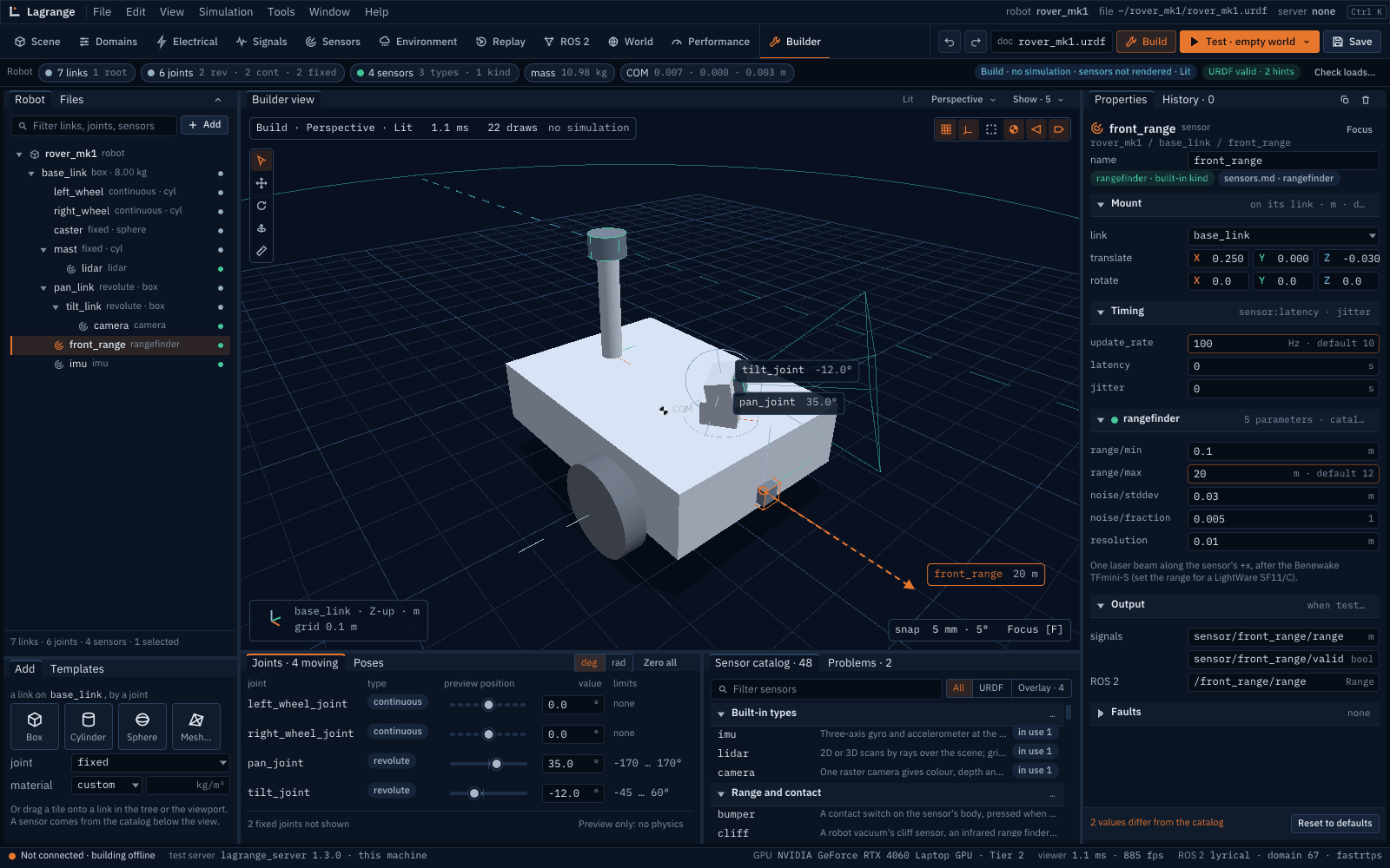
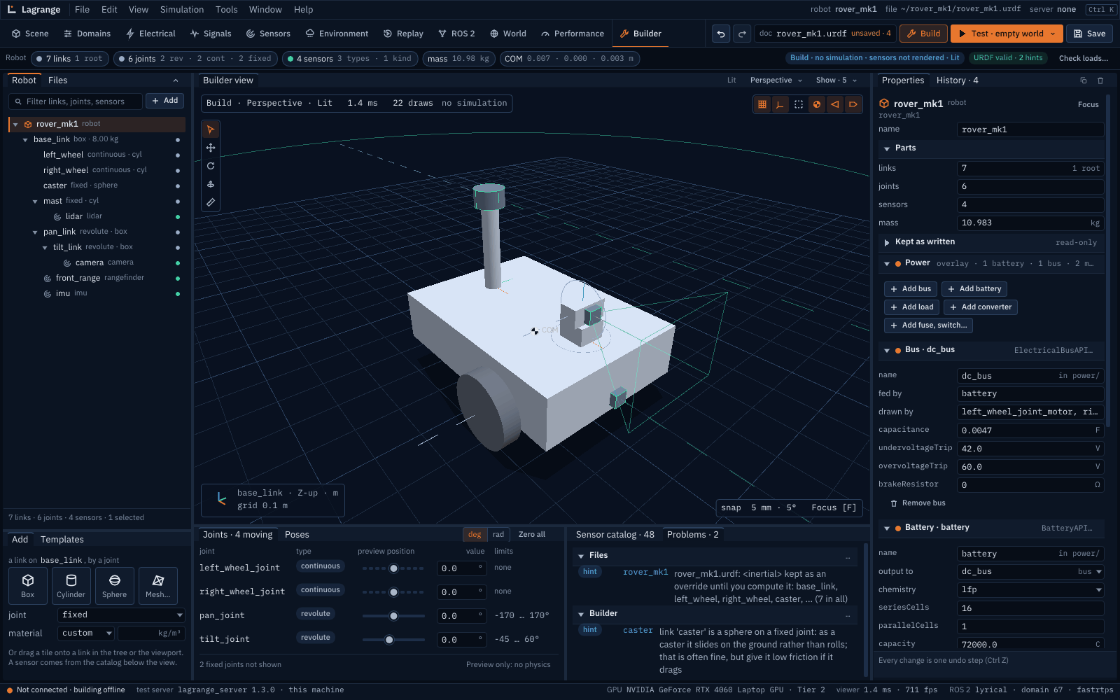
A robot from one box: parts, a revolute joint posed by its slider, a lidar and a rangefinder
from the catalog, a mesh part that collides as its convex hull, then Test, where the slider
drives the joint in the simulator, and Back. Made by tools/videos/make_videos.py builder.
Opening it¶
lagrange viewer --workspace builder                     # a new robot
lagrange viewer --workspace builder --builder-open my_robot.urdf
In the viewer, the Builder tab is the last workspace tab, or press Ctrl B, also on the
launcher before connecting to anything. A .xacro file opens by expansion (xacro must be
installed); its relative meshes are found beside the .xacro. It is never written over: Save
as… writes the robot as a .urdf (Save asks for one).
Build, Test, Save¶
The workspace bar’s right side has the builder’s own controls:
Control |
What it does |
|---|---|
Undo, Redo |
every change is one step (Ctrl Z, Ctrl Shift Z or Ctrl Y); the History tab beside Properties lists them and goes back to any |
|
the file name, and |
Build |
the mode you edit in. Nothing is simulated, no sensor is rendered, the view is drawn Lit: building costs almost nothing |
Test · empty world |
validates the robot, writes it to a temporary file and starts |
Save |
Ctrl S; its menu has Save as…, Open…, Export USD… (runs |
A run the viewer is connected to plays on while you build, unless View → Pause the run while building is ticked: then it pauses while the Builder is in front in Build mode, and plays again when you test (before the viewer leaves it for the test server), go to another workspace or close the viewer.
While testing, the view is the server’s, live, with Play/Pause and Step; Drive lists the ROS 2 topics the robot takes, each with a command line to copy, and Console shows the test server’s log. Back to Build (Esc) stops the test server and returns to the document as it was; Test pressed while the last test server is still stopping starts once it has. If the server refuses the robot, Problems shows why and Build stays active.
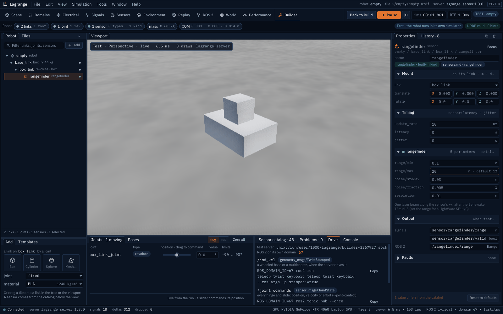
The Robot strip under the workspace bar counts links, joints by type, sensors, the total mass
and the centre of mass; its pill says whether the URDF is valid. Problems lists every finding
(error, warning, hint) with the item it is about; the pill counts the same ones. Test is refused
while there is an error, Save is not. Save writes through a symbolic link to its target, keeps the
file’s permissions and refuses a read-only file; Save as… into another folder rewrites relative
mesh paths for the new file. An autosave goes to
$XDG_STATE_HOME/lagrange/builder/<robot>.autosave.urdf every 30 s (characters other than
letters, digits, _, - and . in the name become _).
Links and joints¶
A new robot is one link, base_link, a 0.3 × 0.2 × 0.1 m box. The Add panel (bottom left)
adds a link on the selected link, by a joint: the tiles Box, Cylinder, Sphere and
Mesh…, with the joint type and material under them as the defaults for the next tile. You can
also drag a tile onto a link in the tree or in the view, or use the tree’s Add menu.
A link needs a mass: choose a material (its density), type a density, or set a mass override in the link’s Properties. The densities are those of the thermal presets; a link without one is a Problem. Mass, centre of mass and the inertia tensor are computed from the shapes, and can be overridden.
In the Robot tree, a child link’s row shows its joint type and shape (revolute · box):
click the joint type to select the joint. Drag a row onto another link to re-parent it, or use the
tree’s Add → Joint between…, which lists the links the selected one can hang from. F2 (or
the name field in Properties) renames the selection: its row becomes a name field, Enter
renames, Esc leaves it. Everything that names it follows: joints’ parent and child, a sensor’s
link, a mimic joint’s leader, the overlay’s entries, and a joint’s <ros2_control> and
<transmission> references (one they name that the robot lacks is a warning); a name already in
use is refused and Problems says why. world is the ground’s name in a run: only a shapeless,
massless root link (a robot fixed to the ground) may take it, any other link named so is an error,
and a mesh named world.stl makes a link world_2. One rename is one undo step. Delete (or the bin in Properties’ tab bar) removes the
selection and everything under it (one undo step). The root that every other link hangs from
stays: a robot keeps a link.
A joint’s Properties: the type (fixed, revolute, continuous, prismatic), parent and child, the origin and axis, the limits, the dynamics (damping, friction) and mimic. Revolute and prismatic joints need all four limits (lower, upper, effort, velocity): the builder invents no defaults, an empty limit is a Problem. Angles are typed in degrees and written in radians.
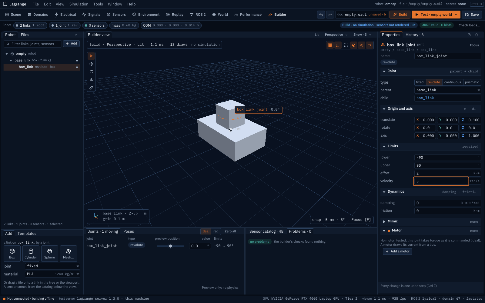
The Joints panel has a slider per moving joint: dragging it poses the robot in the view by
forward kinematics only (nothing is simulated, it is not an undo step); a typed value stops at
the joint’s limits, as the slider does (a continuous joint has none). Poses keeps named sets
of slider positions for this session (the document has no place for them yet, RFC 0016 open
question 10). While testing, the slider or a typed value commands its joint in the test run
(RFC 0016 §7.3: the server’s joint control, its position loop) and the panel shows the live
position (a mimic joint’s from its leader). Until its first command a joint holds where it started on a robot fixed to the
ground, and is free on one that moves about (server/src/JointControl.cpp). A robot that is
passive in a connected run takes no commands, and the panel says so.
Sensors from the catalog¶
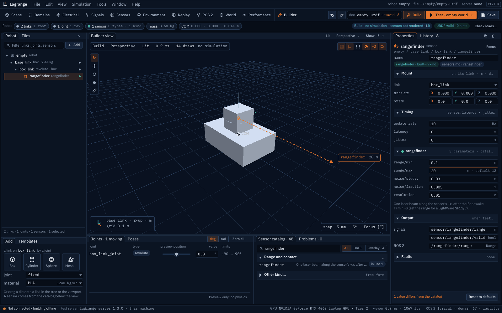
The Sensor catalog lists the built-in sensor types (camera, lidar, IMU) and the built-in kinds (rangefinder, bumper, cliff sensor and the others of Sensors), in groups, with any kinds from installed plugins’ catalog files after them. Filter by name; hover a row and press Add to put it on the selected link, or drag it onto a link. The URDF and Overlay switches show what URDF holds and what needs the overlay file (GNSS, magnetometer, barometer and radar: see Power system). Other kind… adds a sensor of a kind the catalog does not know, with free keys and values.
The sensor’s Properties: its mount (link, translate, rotate), timing (update_rate, latency,
jitter), and one section of the catalog’s parameters with their units and defaults. A value
different from its default has an accent border and its default beside it; Reset to
defaults puts them all back. Output lists the signals and the ROS 2 topic the sensor will have.
Problems checks what the server would refuse at start before Test does: a parameter the catalog
marks required, what a kind needs from the robot (its catalog requires), and sensor rates the
scheduler cannot line up.
Power system¶
URDF has no place for a battery, a bus or a motor, nor for GNSS, magnetometer, barometer and
radar. The builder keeps them in the robot’s overlay file, <robot>.overlay.yaml beside the
URDF (formats §9, as the sample robots have them), which
lagrange_server --overlay and lagrange_import --overlay apply.
Robot → Power (select the robot row): Add bus and Add battery, each from the sample AMR’s or the sample quadcopter’s values or with empty fields. A bus has its trips (
undervoltageTrip,overvoltageTrip, V) and capacitance; a battery its cells, capacity (C), open-circuit curve (ocvSoc,ocvVoltage, per cell), resistances, cut-off and charge limit, and output to, the bus it feeds. The fields are the electrical schema’s (schemas/electrical/schema.usda), with its units; a schema default shows beside a value that differs from it, and a field the loader requires says required while empty.Robot → Power, the parts between buses (RFC 0010, the netlist’s resistors, converters, fuses, switches and diodes): Add load (the sample AMR’s 45 W computer, or empty fields), a load on a bus with its
model(constant_power,resistive, orsignal, which drawsload/<name>/power_demand),power(W), a resistive load’sresistance(Ω) and theminVoltagebelow which it switches off. Add converter, a DC-DC converter from the bus a battery feeds to another bus, with itsoutputVoltage(V),efficiency(above 0, at most 1) andmaxOutputCurrent(A), and its input and output buses. Add fuse, switch…, a resistor, fuse, switch or diode between two buses: itskindfirst, its two ends (a diode’s anode and cathode), itsresistance(Ω), and what its kind needs: a fuse’si2tRating(A²·s), a switch’sinitialState, a diode’sforwardDrop(V). No sample robot has a converter or a branch, so their values start empty and Problems asks for them. Each section lists the signals the run will have:load/<name>/currentandpowered,converter/<name>/output_current,input_currentandloss_power,branch/<name>/current,voltage,stateandloss_power(a switch also readsbranch/<name>/command).Joint → Motor: Add a motor on a revolute, continuous or prismatic joint (a wheel drive or a rotor motor from the samples, or empty), the bus it draws from, and its winding, torque constant, gear and current limit. The motor is named
<joint>_motor; the Motor section lists the signals it will have (motor/<name>/current_q,bus_current,joint/<joint>/torque).Names: each part’s
namefield (its prim ispower/<name>, a motor’s<joint>/<name>) renames it, and every connection to it follows: a battery’s output to, the motors’ and loads’ bus, converters’ and branches’ ends. The run’s signals take the new name (bus/<name>/voltage). A name used by another part, a link, a joint or a sensor is refused, with the reason under the field.GNSS, magnetometer, barometer, radar come from the catalog like any sensor (the Overlay switch lists them) and are edited in the same form. The overlay has no mount pose: they sit at their link’s origin, so put them on a link placed where they are.
Problems checks what the loader would refuse: a required value missing, a value out of the
schema’s range (a negative resistance, an efficiency over 1 or of 0), an ocvSoc that does not
ascend or is not as long as ocvVoltage, a motor on a fixed joint or a second motor on a joint, a
motor, battery, load, converter or branch without its bus, a converter or branch with the same
bus at both ends (both its dropdowns are outlined red too), two converters onto one bus (the network simulates one per output bus), a fuse
without its rating, a load with neither a power nor (resistive) a resistance, and a bus that no
battery reaches: through a converter from a fed bus, or a branch to one (a diode only from its
anode). Converters in a loop (a → b → a) are a warning: the network runs them, but power goes
round. A value set for another kind of branch (a fuse’s drop) is a hint. Test runs the server with the overlay
(--overlay), so the run has bus/<bus>/voltage, battery/<battery>/soc and the motors’
currents in Signals; Into the connected run sends it with the robot
(ImportRobot.overlay_content), where a passive robot’s names carry its own as a prefix
(bus/rover_mk1_dc_48v/voltage). Save writes the overlay beside the URDF and Open reads it
back. Anything else an overlay holds (thermal nodes, rotors, wheels) is kept as written and
listed under Overlay, kept as written; comments after the file’s first lines are not kept
(the builder writes each value’s unit as its comment).
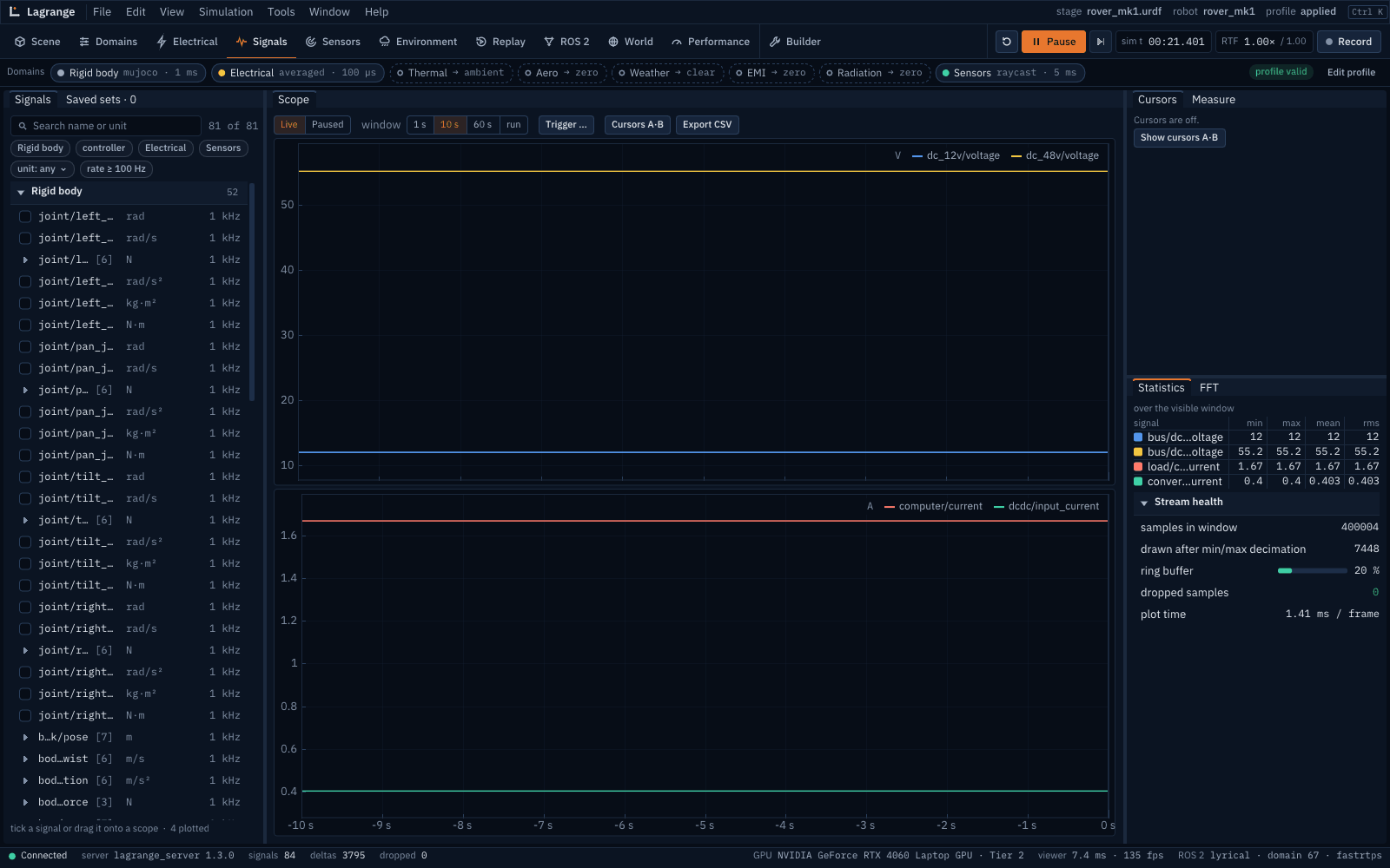
A 12 V rail, as a test of the rover: a converter from the 48 V bus to a dc_12v bus with a 20 W
computer on it. Test, then Signals (Ctrl+4): bus/dc_12v/voltage holds 12 V, the load draws
20 W / 12 V = 1.67 A, and converter/dcdc/input_current is that power over the efficiency
from the 48 V bus (viewer/test/test_builder_power.py).
Meshes and how a link collides¶
Mesh… in Add takes an STL, OBJ, DAE or glTF file (the file dialog with a window, or a path typed in its field; tick file in millimetres for a scale of 0.001), read as the simulator reads it. A closed mesh’s mass comes from its volume; a mesh that is not closed is a Problem and its mass comes from its convex hull.
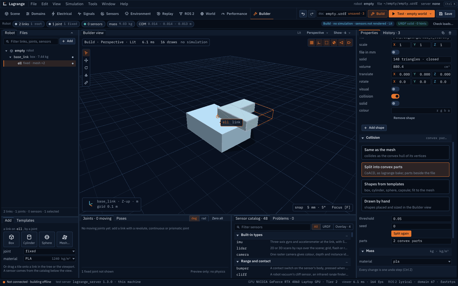
Each link’s Collision section in Properties chooses how it collides, one of four:
Same as the mesh: the visual mesh collides. The simulator collides a mesh as the convex hull of its vertices (at most 256 points), so the builder draws that hull; a concave mesh is marked its inside will be filled.
Split into convex parts: CoACD, as
lagrange bakedoes, with its threshold and seed. The parts are written beside the robot’s file in<robot>_collision/(save the robot first). It needspip install coacd.Shapes from templates: a box, cylinder, sphere or capsule, and Fit to mesh: the tightest box or cylinder about the mesh’s principal axes, or the enclosing sphere, to edit from there.
Drawn by hand: shapes placed over the translucent mesh in the view and sized with the gizmos and size handles, several per link.
The choice is written as a lagrange_collision attribute on the link (the loaders ignore it), so
the file reopens with the same choice.
The Builder view, gizmos and keys¶
The view draws only the robot being edited. The tools on its left:
Key |
Tool |
|---|---|
Q |
Select |
W |
Move: the selected link’s joint origin, or the selected sensor’s mount |
E |
Rotate |
A |
Joint axis: drag the ring to snap the axis to x, y or z of the parent; Shift for any direction |
M |
Measure |
F |
Focus on the selection |
Esc |
drop a drag in progress; while testing, Back to Build |
Moves snap to 5 mm and 5° (hold Ctrl to toggle the snap). The toggles at the top right show the grid, frames and joint axes, collision shapes, the centre of mass and inertia boxes, sensor frustums and rays, and names.
Templates¶
The Templates tab beside Add opens a starting robot as a new document: a differential-drive
base, a three-joint arm and a pan-tilt head (assets/robots/templates/). Save asks for a file;
the template stays as it is.
Not supported yet¶
Where the robot starts when it goes Into the connected run: where its file puts it (the protocol’s
ImportRobotcarries no pose; Start at… applies to a test server’s own run).Poses are kept for the session only: the URDF has no place for them (RFC 0016 open question 10).
Thermal nodes, rotors and wheels in the overlay: kept as written, not edited (the Power section edits buses, batteries, motors, loads, converters, fuses, switches and diodes).
Opening USD or SDFormat robots (phase 4); the builder opens URDF and xacro.
Free-form modelling: the builder places primitives and meshes, it is not a CAD tool.
Headless¶
For scripts and tests the viewer runs the Builder without a window:
lagrange_viewer --headless --size 1600x1000 --workspace builder \
    --builder-open robot.urdf --input "3:click:40,862" \
    --builder-save out.urdf --screenshot out.png
--input takes keys by name too (5:key:f2, 7:key:delete) and FRAME:world:FILE, which
makes FILE Test’s world as Browse… would. --builder-save writes the document at the end (not when --builder-open failed: then the
viewer exits with 5 and writes nothing); the JSON report on stdout has a builder
object (links, joints, sensors, the mode, the history, Problems). viewer/test/test_builder_acceptance.py
builds a robot this way from start to Test and back and compares the file with a golden one.